As I was learning Maya, we used Photoshop as a way to texture our creations and see what they would look like. This is an example of a simple Mario cube with the appropriate texture applied to the cube I made in Maya.
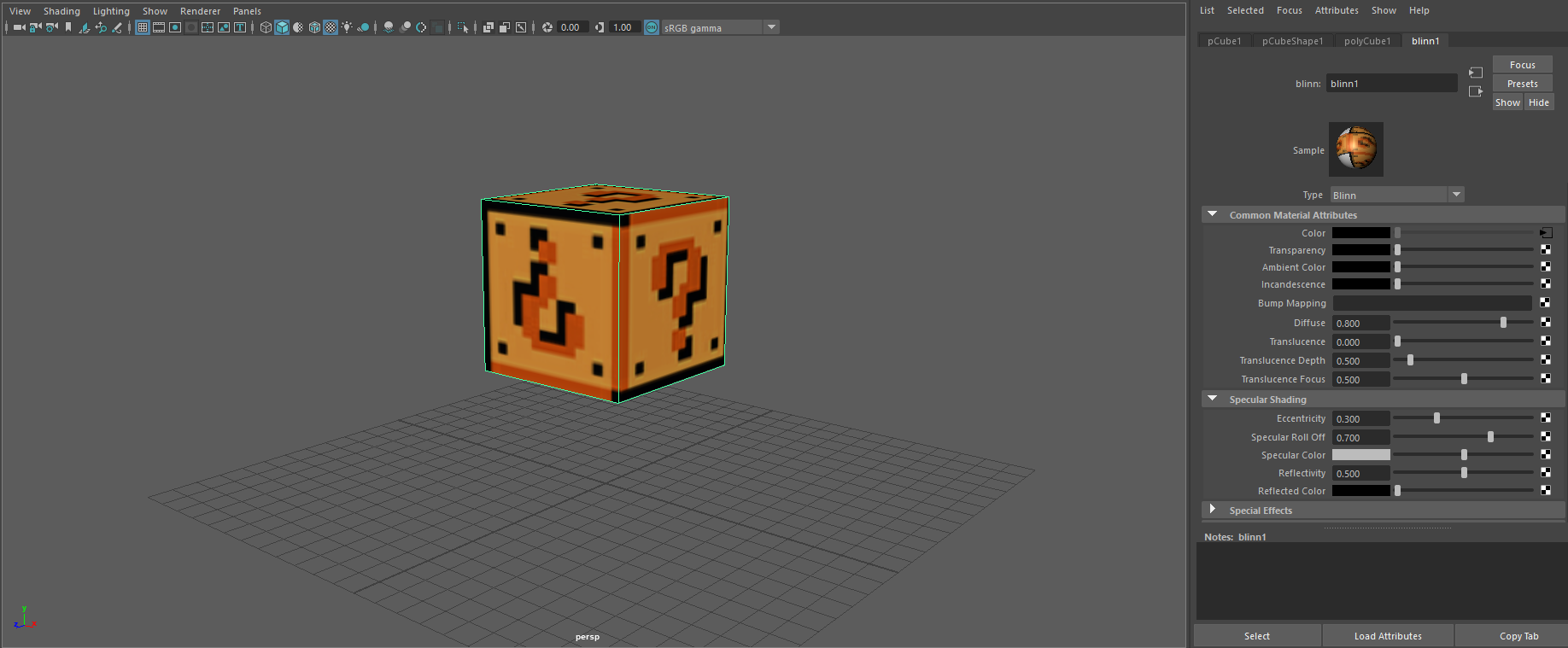
As I was learning Maya, we used Photoshop as a way to texture our creations and see what they would look like. This is an example of a simple Mario cube with the appropriate texture applied to the cube I made in Maya.
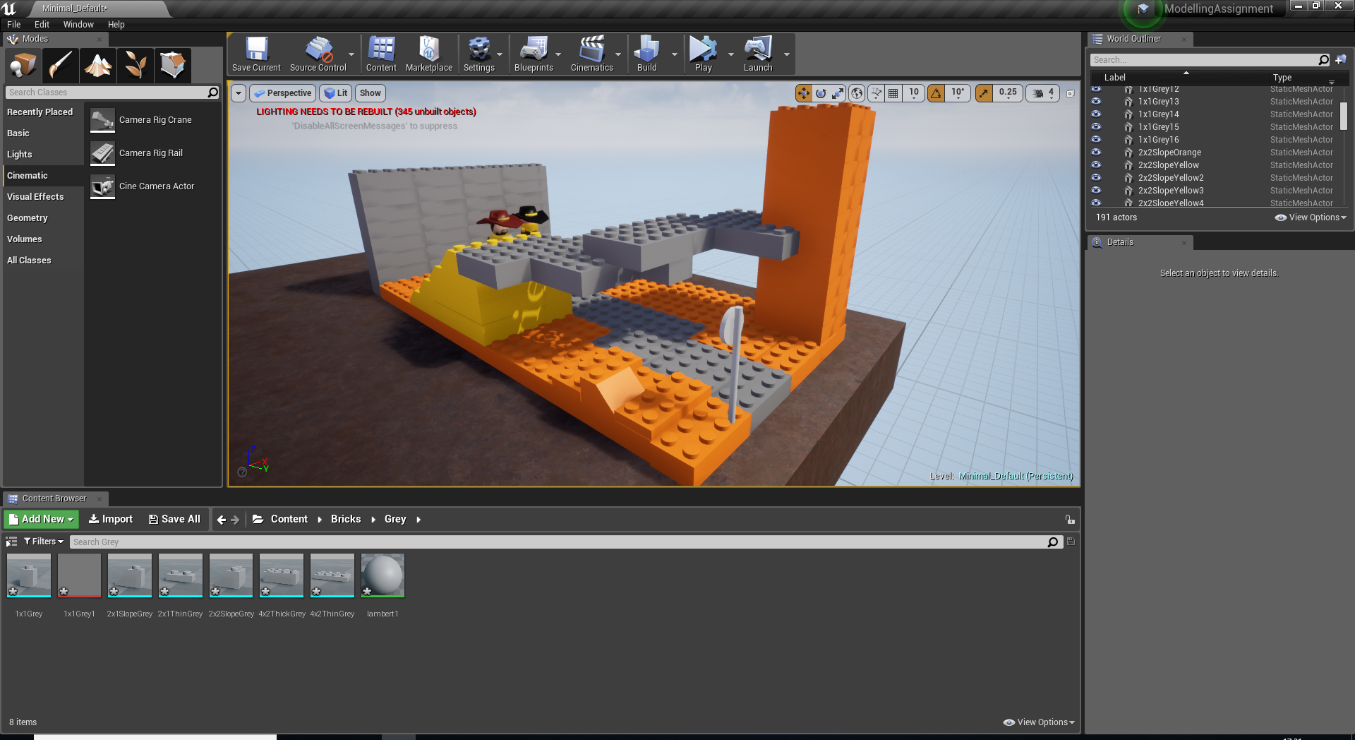
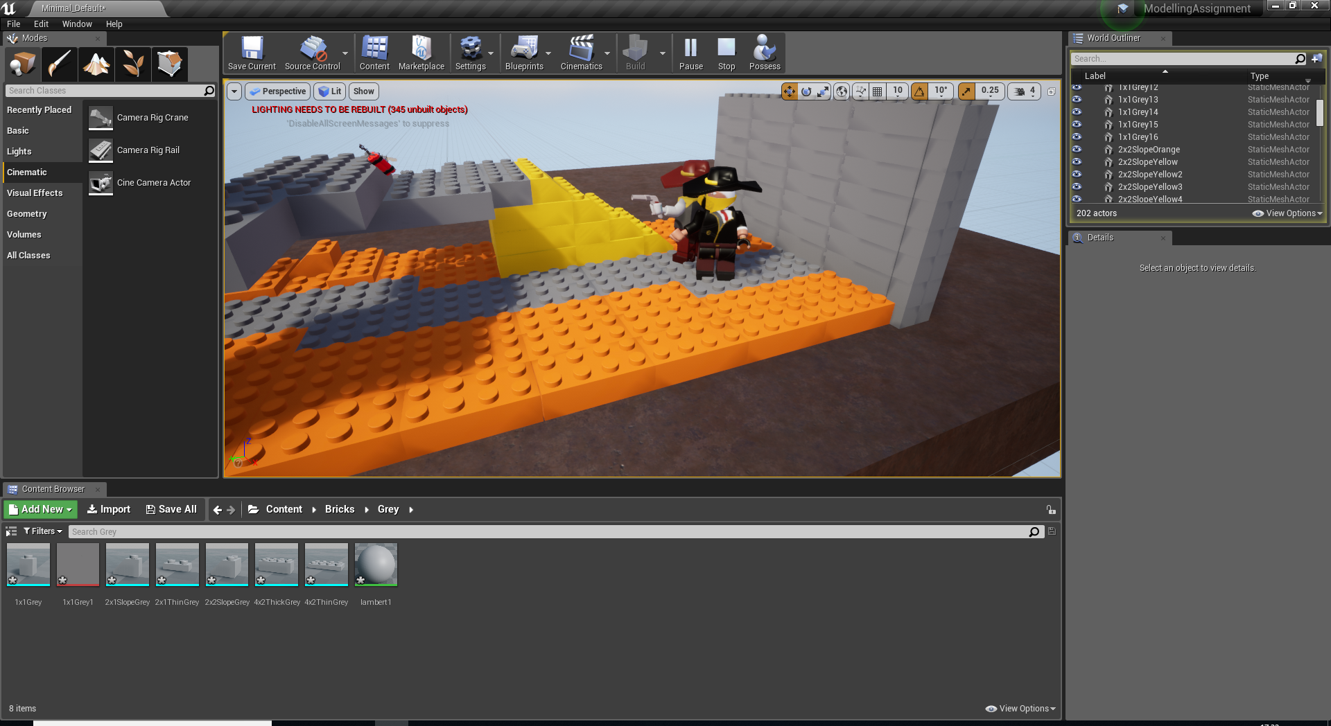
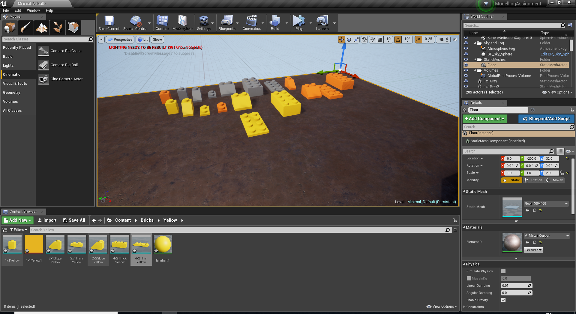
Being completely new to Unreal, I taken a lot of time out to learn how to use it at its very basic level. This helped me figure out what I was doing to start building my scene. Using the LEGO blocks that I created in Maya I created a completely custom scene and placed my characters inside. The main challenge I found with this was figuring out how to use my animations from Maya in Unreal. If I was going to do anything in Unreal again I would take more time out to find out exactly how to use the engine in every way to get the results I want. These are the screenshots that I have from importing my objects and organizing them, placing my bricks into Unreal and capturing the animation at its midpoint and ending.


Animating the characters in Maya was the hardest challenge for me to overcome. This is because some of the characters and their objects weren’t taking the path I wanted them to take and I ended up having to go frame by frame editing multiple pieces to make the animation as smooth as possible. Having these issues gave me some good experience in dealing with animation as I found that the longer I was working on moving the objects and trying to time certain objects it became almost second nature. These are a few of the screenshots of the timelines where I have changed objects to move.

I used Mudbox to texture all of my objects ready to be put into Unreal. I decided to use Mudbox because I believed that the process would be a lot easier me and I could get more detail with Mudbox rather than something like Photoshop. I found out that when coloring in Mudbox I was using the model before it has been smoothed, which when going back into Maya and placing the textures back on the objects was an issue as the colour would move to how the object was smoothed. However, after knowing the object was not going to be smoothed in Unreal I didn’t go back to amend the textures as they were going to be fine in the engine. These are all of the examples in which I used Mudbox to texture my models.

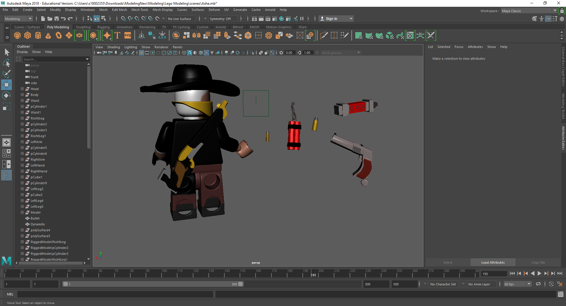
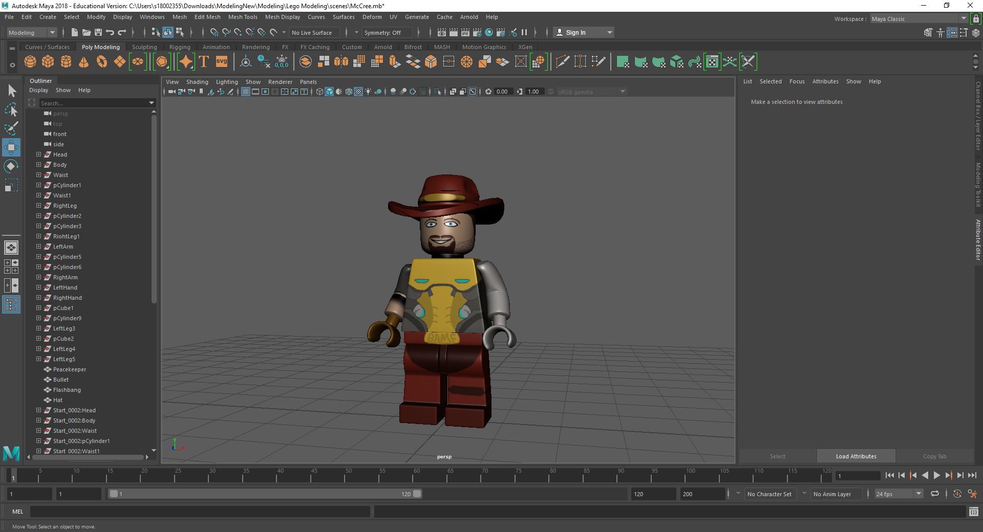
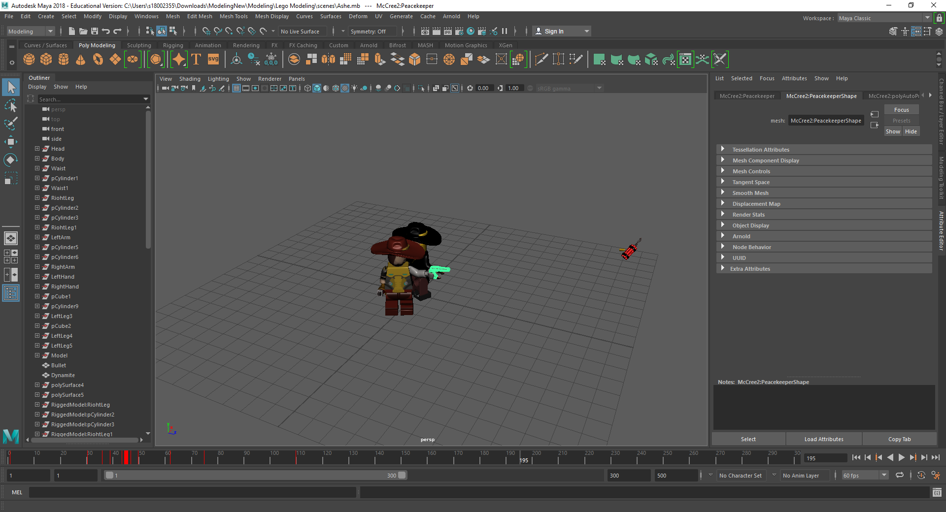
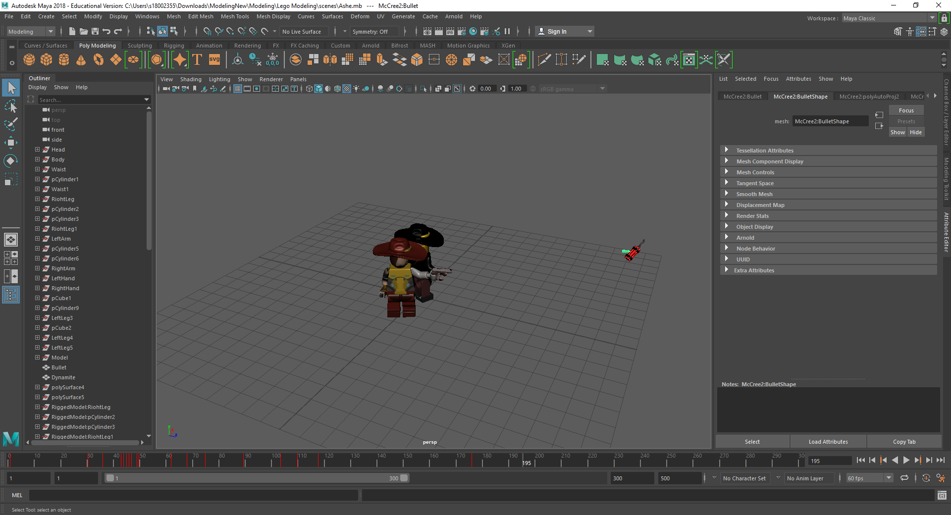
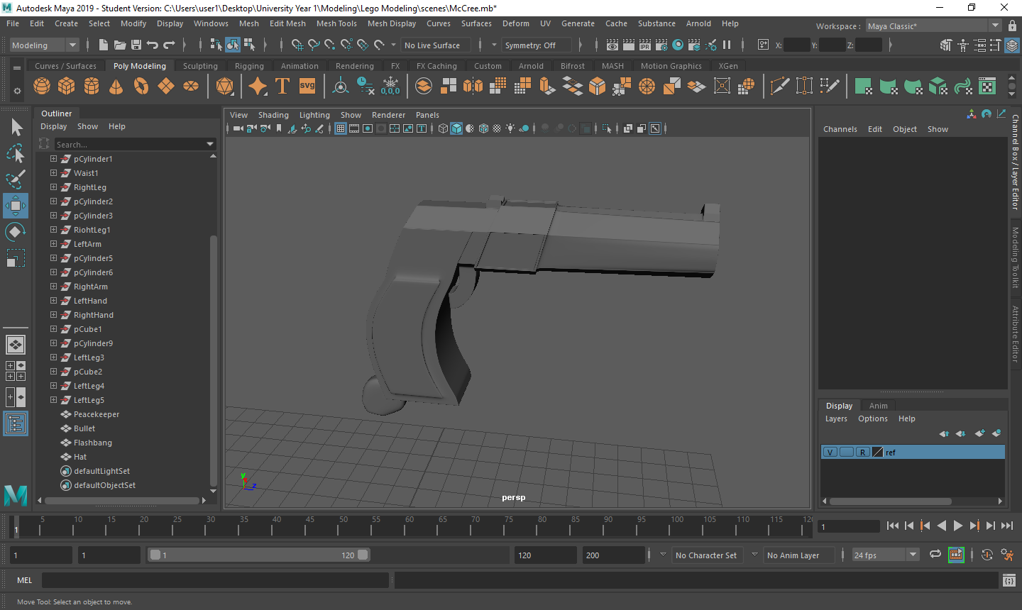
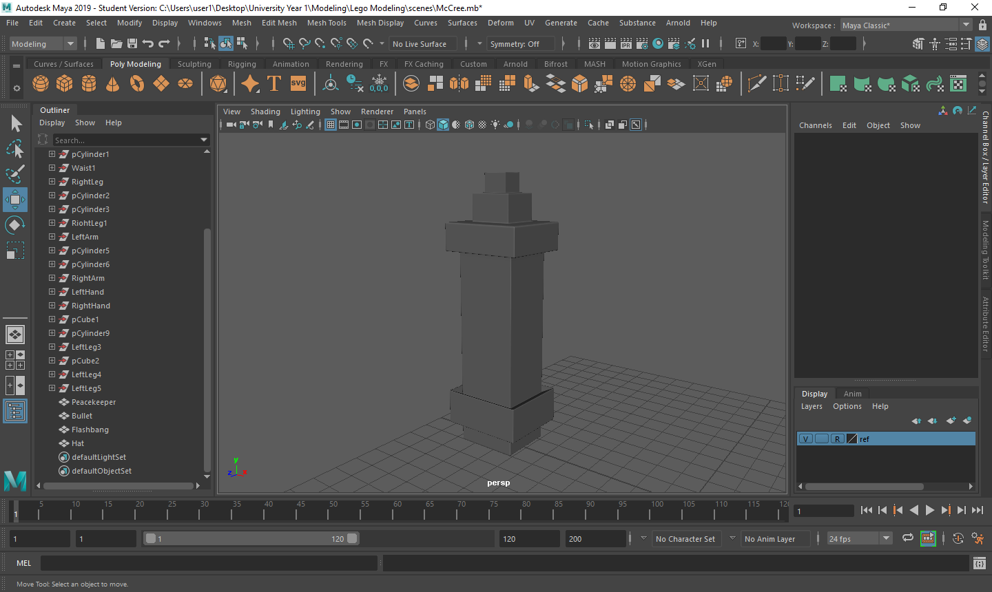
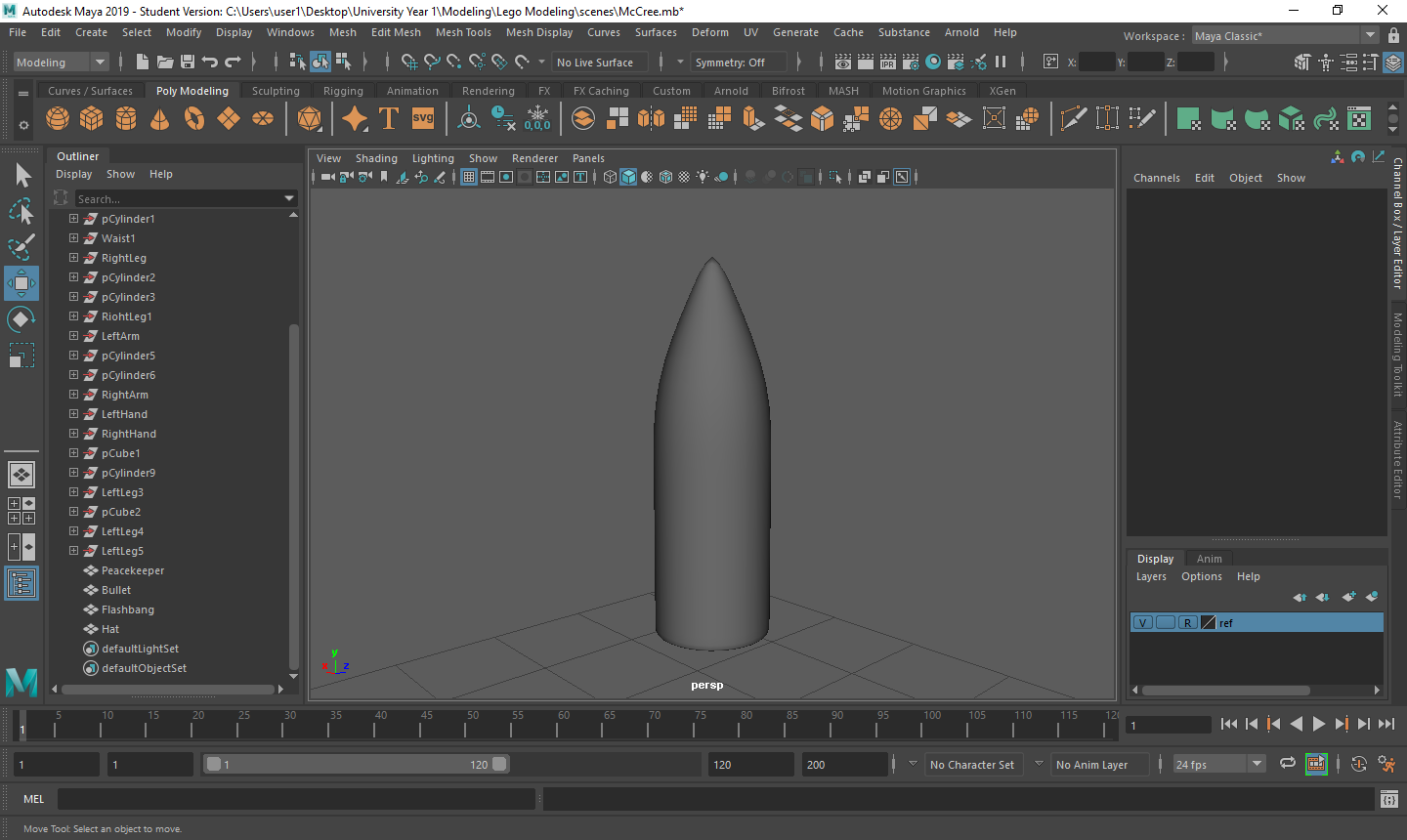
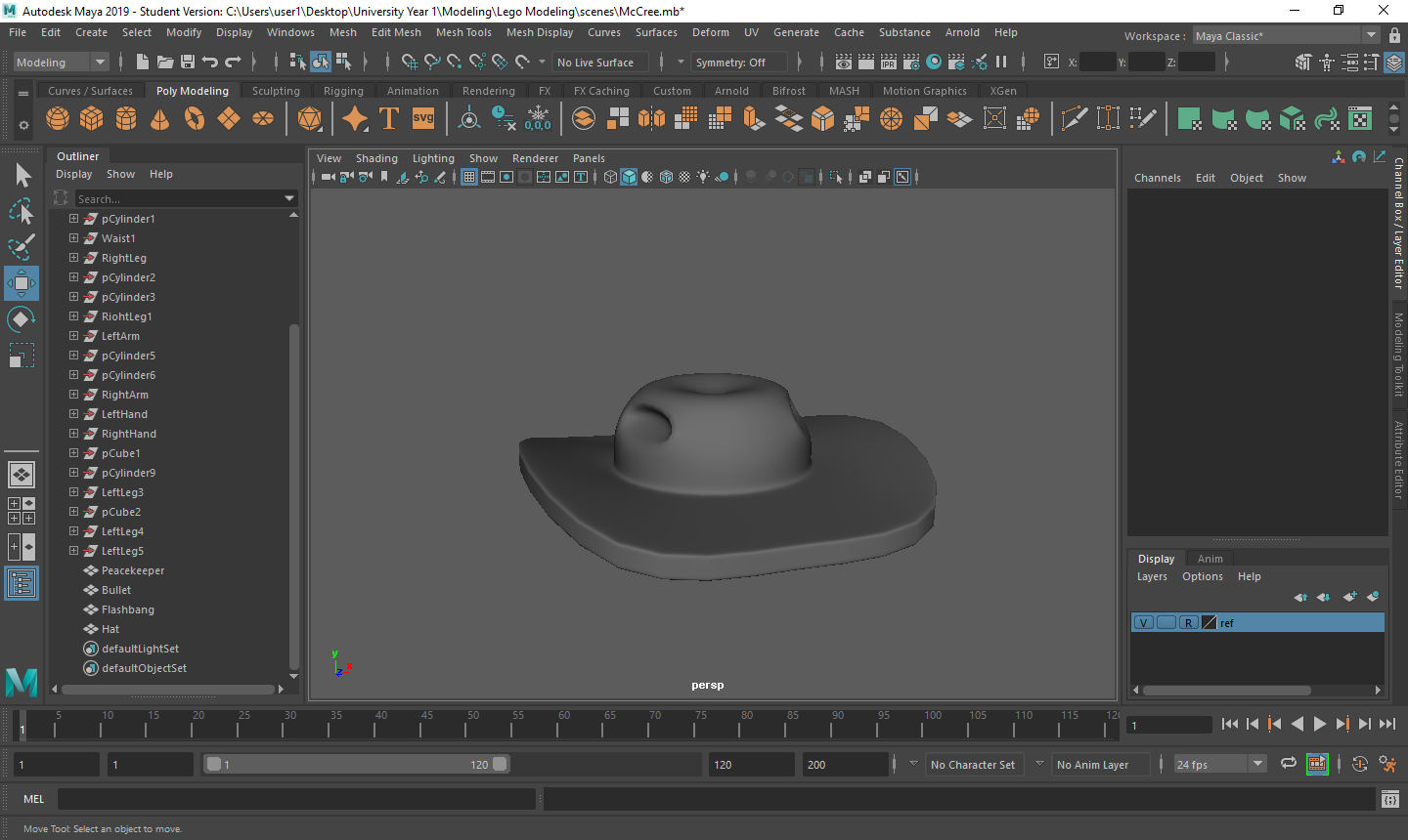
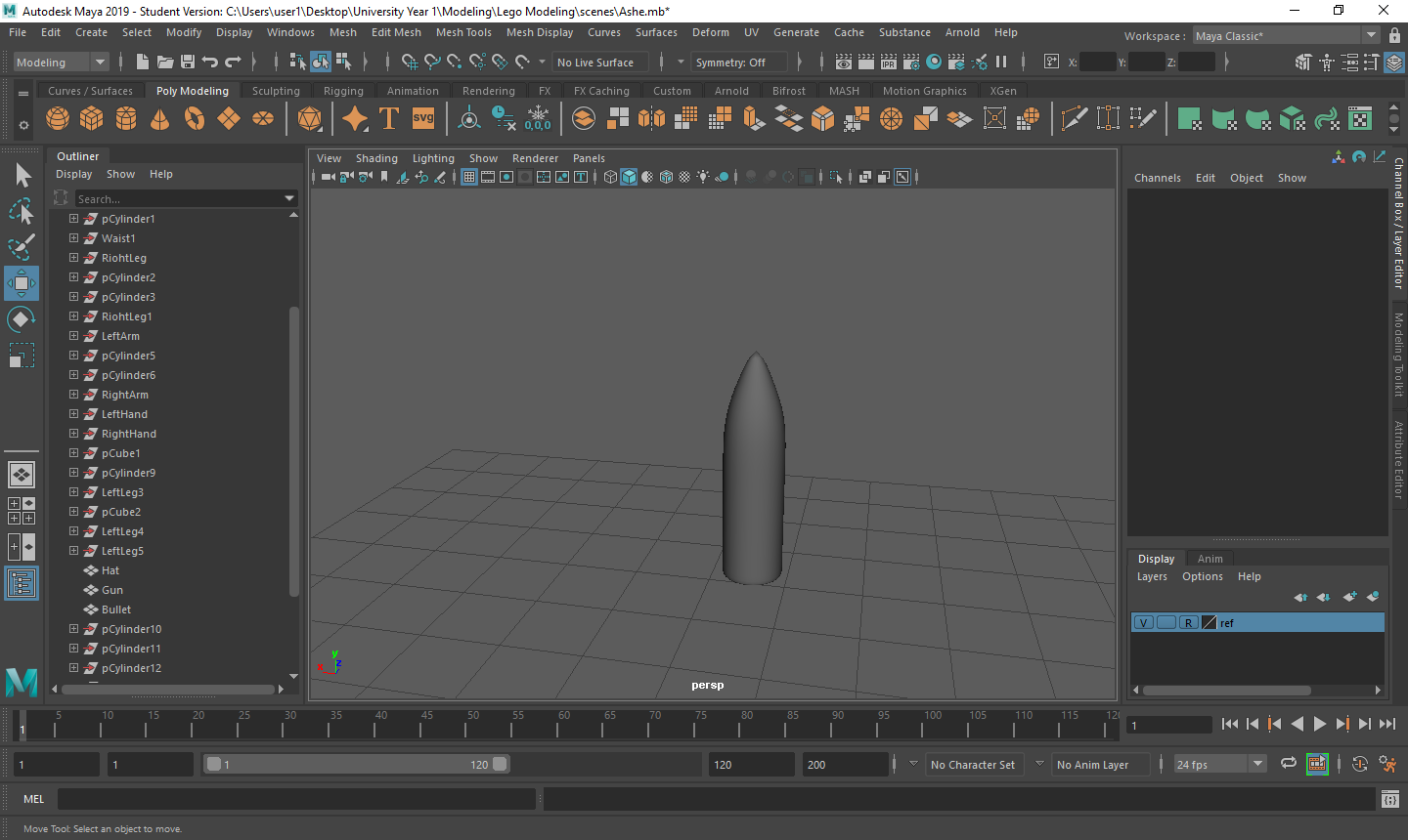
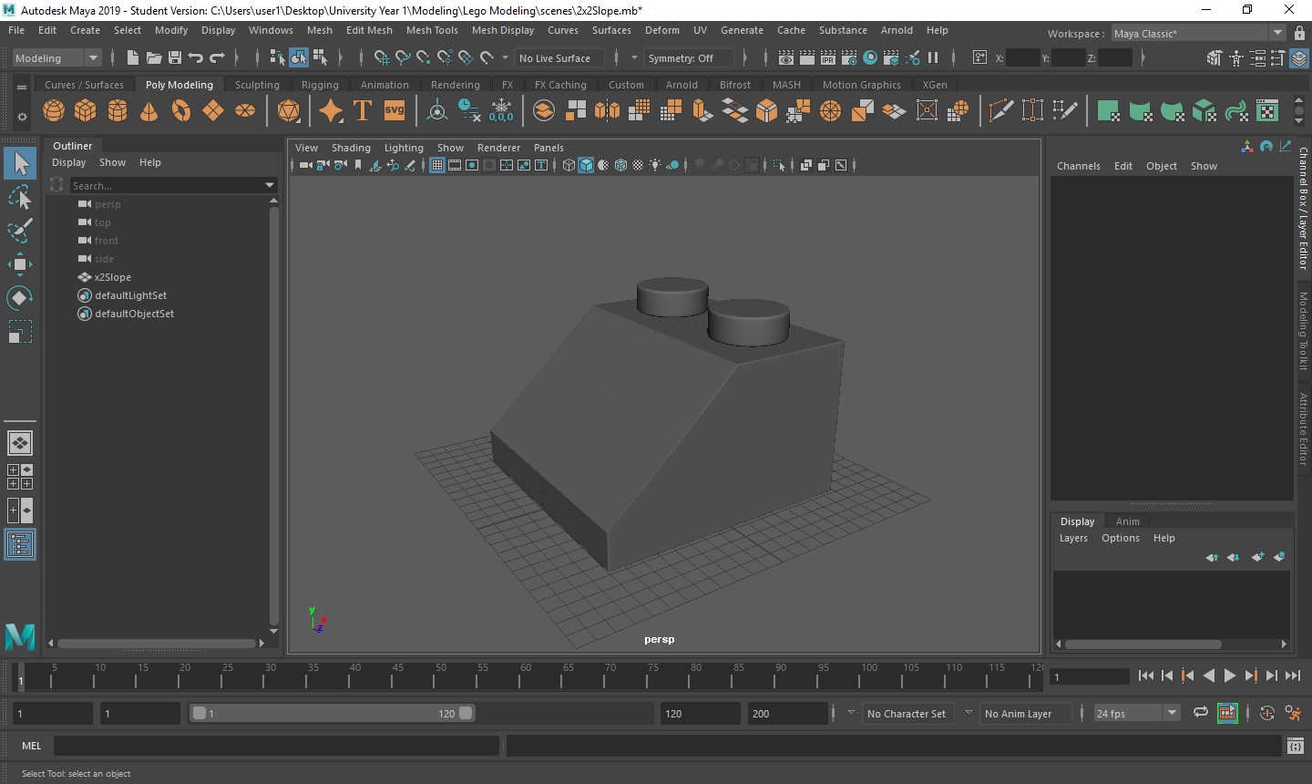
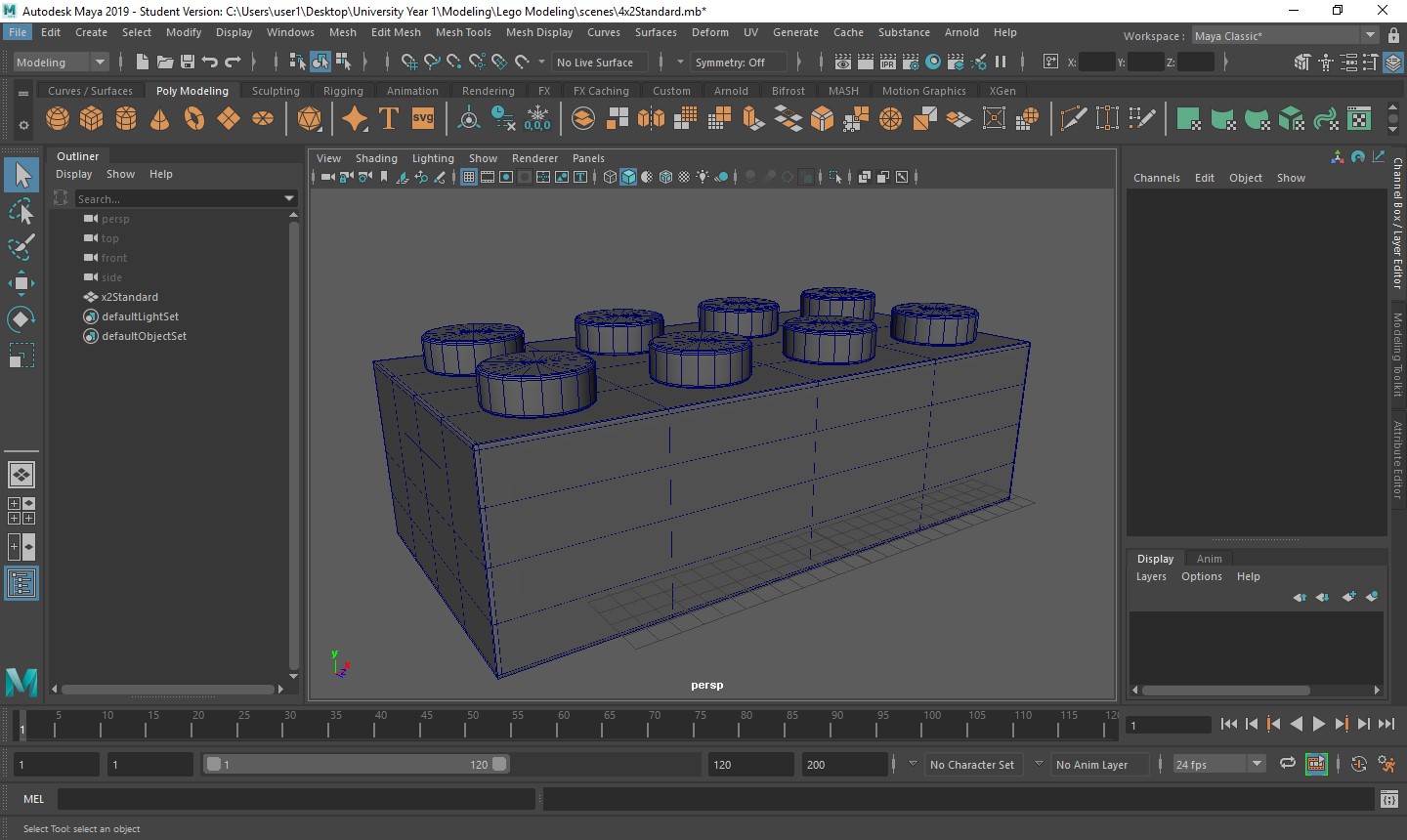
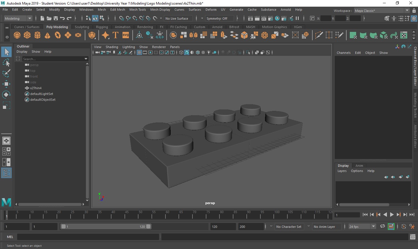
Creating the custom pieces for my scene was a very good exercise for me. When creating the model I was working with 2 images that I could scale from and when completed, I knew it would look like a realistic LEGO model. That particular way of building was very useful to me starting Maya as I knew when I was getting the objects right and allowed me to experiment with a few techniques to see if they would work. Going onto the custom pieces, not having that “crutch” of the images was a challenge at the beginning but it also allowed me to express some freedom in the way I working. With the model scaled perfectly, I knew that I could scale the custom pieces to the model and they wouldn’t look out of proportion. Using all of the techniques that I learned from creating my model I knew I could come up with some very good pieces. The guns were the hardest the create as they are intricate objects that have a lot of detail. To combat this, I decided to dumb it down into it simplest form to make sure I had a lot of pieces I could use to build my scene. These are all of the custom items I created for both characters and the environment.


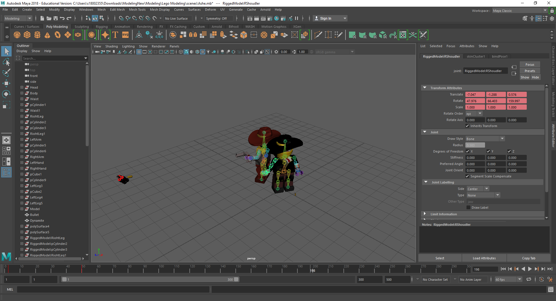
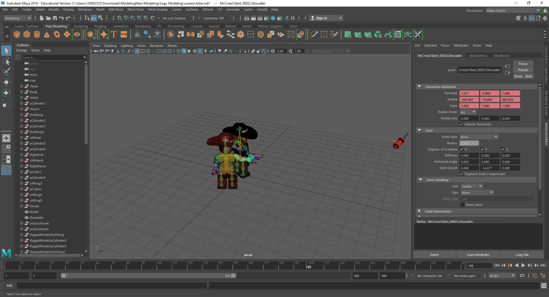
Rigging the LEGO model was a challenge for me. Firstly, with the amount of individual parts I had, making sure that all of the mapping weights were correct took a long time as sometimes there would be one vertex being affected by something it shouldn’t be and that would throw the model out of shape. Secondly, there was many iterations that I went through to make sure that it was perfect for the character I was using. Having parts that had holes in them or were attached to a certain joint also took a couple tries to figure out what I was doing.

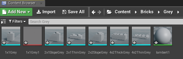
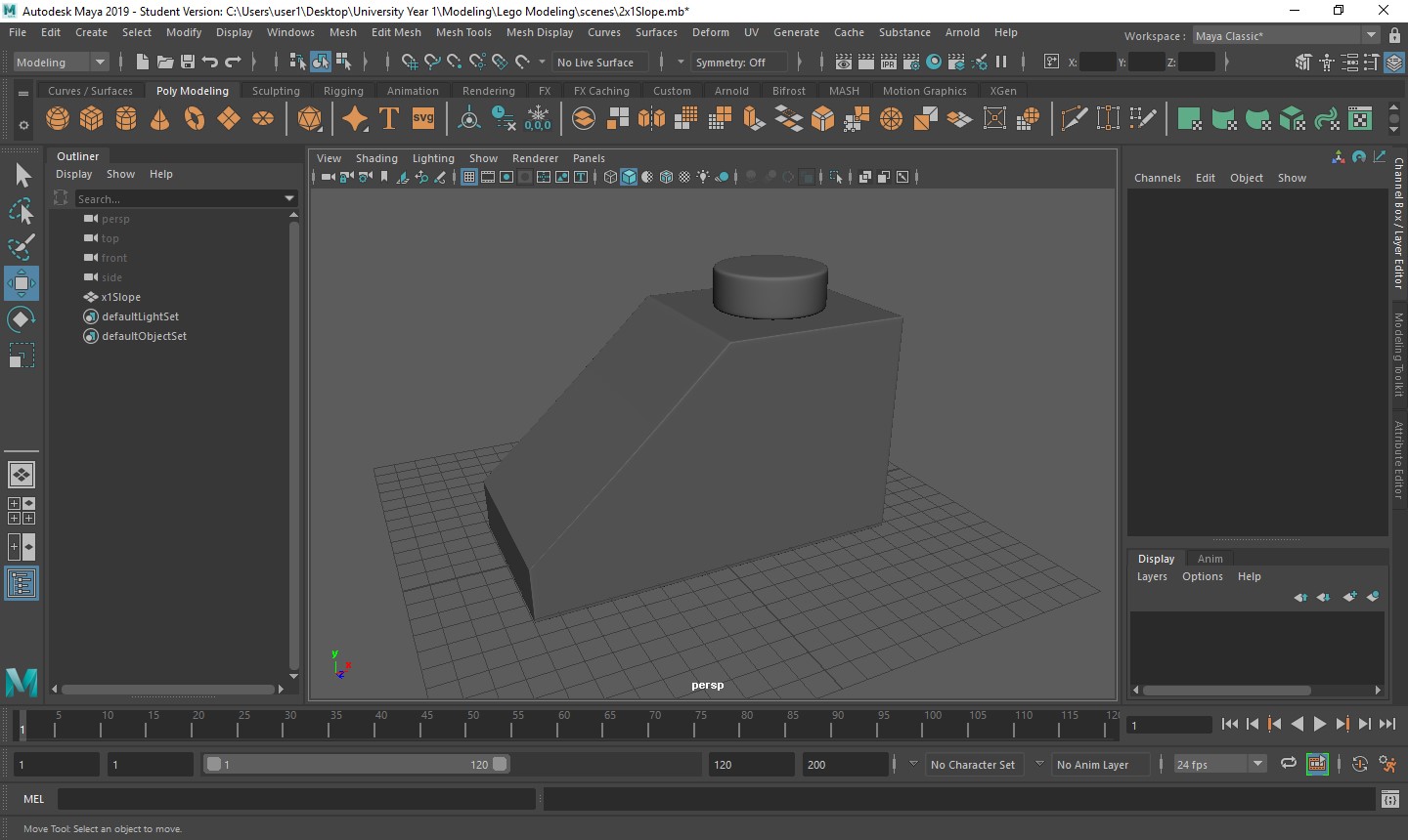
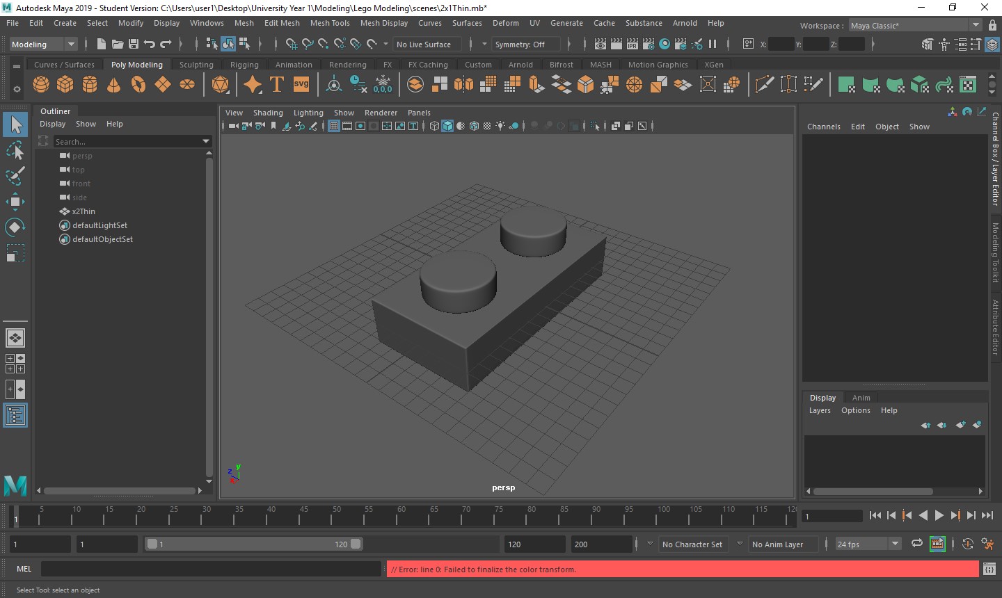
Creating all of the LEGO blocks was a really quick process as they are very simple objects, being a rectangle and cylinders. These are a few examples of what I made in Maya that I will be putting into Mudbox to texture and import into Unreal Engine to create a scene from Overwatch.
Creating The Work Space
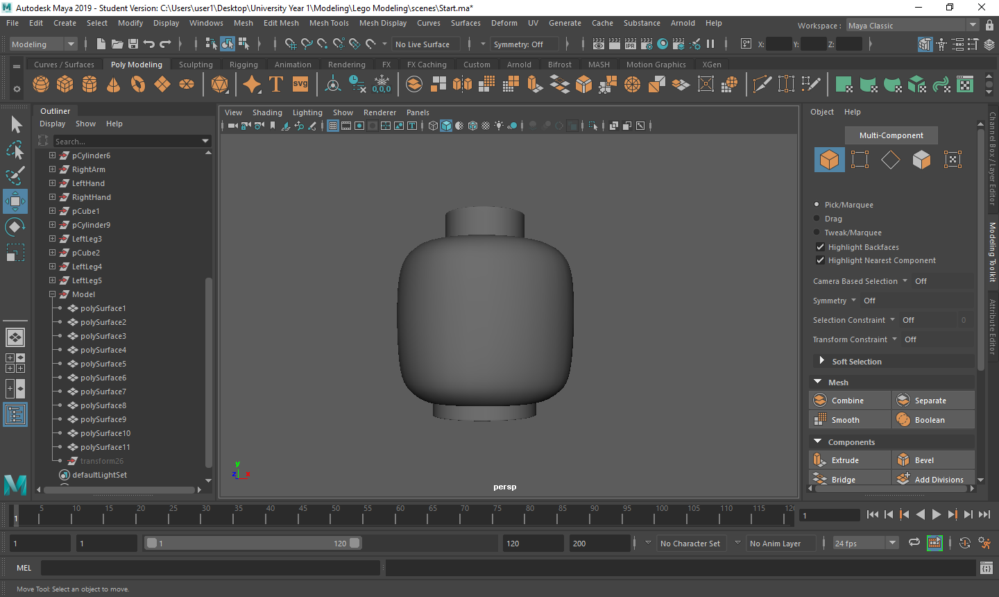
The first thing that I wanted to create when going into this project was the model itself. I figured that I would create one model and duplicate them to make different characters for my assignment. Also, creating the model was going to be the hardest thing to create in this project, so if I put a lot of hours into it I was going to learn how to use all of the different tools available to me, and would make a lot of building afterwards a lot easier. With this in mind, I found two images that would show the front and side view of a standard LEGO model. This would give me the accuracy I needed to create a model that looks almost identical to the real pieces you can buy. I then imported these images into Maya, and moved them around until they were in the correct places. I knew that they were in the right places when I could create an object and it would be in proportion with the images that were behind the object itself. I then made sure that in the settings/preferences menu that the work space was set the millimeters and not centimeters. This is because of the model and size we are working with. If we used centimeters, the object would 10 times larger that it is supposed to be, and we can be more accurate with our dimensions in millimeters rather then centimeters. Now I have my work space set up, I went onto modelling the character.
Creating The Head
To create the head, I made a simple cylinder and moved it to correspond with the images. I then changed the variables like the subdivisions axis down to 8 and the subdivisions caps to 3. This means that I have less vertices to control and when I smooth the object, it will still look like a LEGO head. When I changed to caps, I knew that this was going to be for the extrusion for the neck and top of the head. I then moved the outside vertices so that they were in-line with my images for the shape of the head, and the vertices for the extrusions so that were in proportion with the scale of the head, ready for extrusion. Once the object was ready, I beveled the top and bottom ring of the cylinder so I could keep the shape of the head when it was smoothed. I set the fraction to 0.1 and the segments to 3. These are settings that I will be using for the majority of beveling I do, unless stated otherwise. This is so I had a very small space between the edges I was creating, giving me a smooth curve when the head was finished. I then extruded both the top and bottom ring inside the cylinder faces, which is why the caps was set to 3, for the neck and top of the head, and used the scaling tool to make sure the proportions were correct. I also made a final extrusion to the inside circle of the bottom of the head. I pulled to up into the object to show the area where the head be placed onto the torso. Finally, I beveled all of the rings that I created through extruding the object is different ways, setting my fraction and segments to the above, to give me the smoothness that I wanted, but also keep the shape of the object to look like a head. Without doing this, I was going to get a shape that looks more like a sphere, rather than a cylinder.
Creating The Torso
With the head now completed, I found that the best next step was to create the torso. I chose this because everything is connected through the torso, including the head, and once scaled appropriately, it would give me 2 directions in where I want to go, being the arms and going down into the wrists and hands, or through the waist and down into the legs. To create this object I made a cube, moved it so that the top face was connected with the bottom face of the neck, and scaled out the cube so it was in-line with the images that I have either side of it. I then set the subdivisions height, depth and width to 4. This is so I didn’t get any “engons” in my object. This is where a face has more than 4 sides to it and the software has a hard time with smoothing the object, so by breaking it up into more faces we can avoid this issue. After this I needed to make sure that object was molded to look like the torso of a LEGO model, as they have more of a trapezium shaped body. To achieve this, I selected all of the vertices at the bottom of the cube, and used the scale tool to make it wider until it hit the edge of the image behind it. Once completed, I extruded all of the bottom faces, pulling them down to connect to the waist I needed to build. This is because on an actual LEGO torso, they have a small connector there and isn’t just a full trapezium. Finally, I beveled all of the edges, including the edge where I extruded the faces to get the shape I wanted when smoothing the object.
Creating The Waist
I decided that after creating the torso, doing the waist would be beneficial to me as it would still keep my options open and it looked like one of the easier pieces to make. I created a small cuboid that would fit underneath the torso to its exact dimensions and was in the guidelines of my images. I then added 4 to all of the subdivisions to avoid the engons and to move the vertices to create a smooth curve through the side of the object where the leg would eventually fit in. To do this, I used the soft select tool, which gave me the ability to move one vertex and still have control over others around it to create the curve. With this in place, I added another edge loop in the center of the object going from front to back and moved both of the center edge loops to give me the dimensions I needed shown from the image. This is so I have a place where I could add the extra cylinder that connects the two legs. I then created a cylinder and rotated the z axis by 90 degrees. This is so that the cylinder was ready to be edited to create the extra part. Changing the Subdivision Axis to 8 and keeping the rest of the settings as default, I scaled the cylinder accordingly so it was ready to be merged with the rest of the waist. To merge them, I firstly combined both objects. I then deleted the faces where the cuboid and cylinder would meet on both objects, selected the edges around the faces that I just deleted and used to the bridge tool to connect them. By selecting just the cylinder faces, I could move into place and start adding edge loops to bevel the object. I did this so I had more accuracy over what was being beveled as I could manually add everything I needed into the object.
Creating The Arms
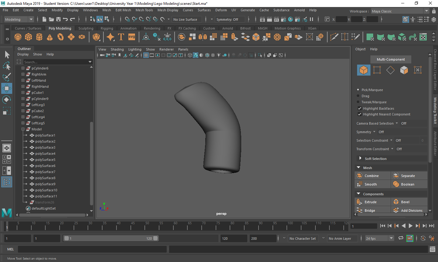
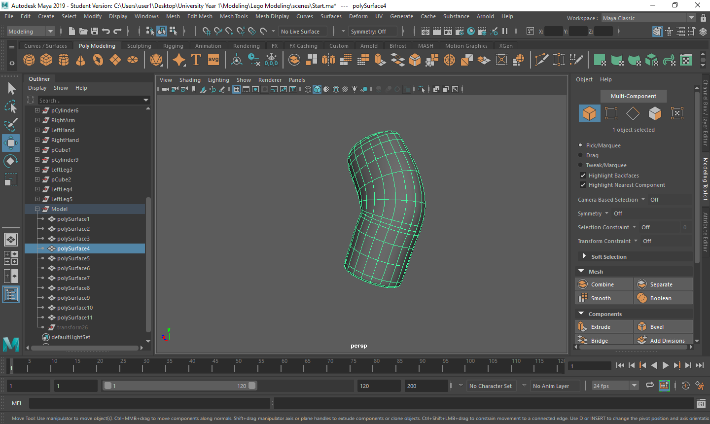
Creating the arms was a lot more time consuming than I first imagined and I thought of a couple of different ways that I could achieve what I wanted. I could of either created a cylinder and rigged a bone structure into, where I would manipulate the joints give me the shape a wanted or the option I chose, which was to create a very small cylinder where the wrist starts, rotating the initial cylinder until it was correctly in position, and extruding the top face out multiple times, manipulating each extrusion using the rotate and scale tools to get a very accurate shape. I kept the axis at 20 and changed the caps to 2 for a later process. As I working from the wrist up, I knew that the main issue I would have is with the rotation around the elbow to do the upper arm and shoulder. The way I got around this was by making very small extrusions whilst I rotate around to create the elbow. I made a lot of these extrusions to get the accuracy I needed. Now I had the arm that I wanted, I needed to make a final extrusion at the bottom to create the hole where the wrist was going to be fitted. Using the circle that was there from changing the caps, I modified the circle so that it was in-line with the image I was using so that the wrist I was fitting later on wasn’t out of proportion with the arm. I then selected all of the faces and extruded into the arm to create the hole. Once I was happy with the length of the extrusion, I simply deleted the faces I used for the extrusion so it have the illusion that the hole was going all the way through the arm, where it really all hollow baring the extrusion. All I had to do now was duplicate the object and flip it so that I had both arms now ready.
Creating The Wrists/Hands
To create both of these objects, I decided to split them both into separate objects. I did this because I found it easier to use a cylinder that was beveled and rotated so it fit into the hole in the arm for the wrist and leave most of the work to create the hand. For this particular object, I started with a cylinder with an axis of 10 and caps of 2 and rotated the x axis by 90 degrees. I put in the caps so that I could use it base where the hand will arch so it looks realistic. Using the reference images to scale the inside circle vertices so that they matched was the first step. I then extruded one of the inside circle faces to the other side and deleted both faces. This is so I had a cylinder you could see completely through. to make sure that I still had the edge flow in the object I connected the vertices from the extrusion to the corresponding vertex at the end of the shape. I then deleted the faces at the bottom of the shape give it an opening where the hand can grab something. I used the fill hole tool to make sure that I had no double vertices and then added some edge loops through the shape for the next part. Using the vertices that I have just got from adding the edge loops, I used the soft selection tool to move them in a way that I would get a smooth curve on both sides of the shape going to the back of the hand. Once this was completed, I used the edge loop tool to add my own bevel and then duplicated the whole object to have both of my hand completed, leaving only the leg to finish the model.
Creating the Legs
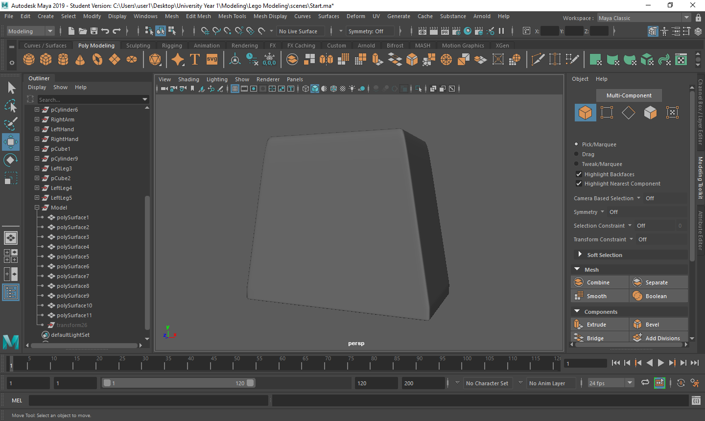
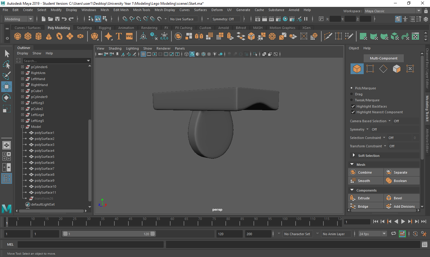
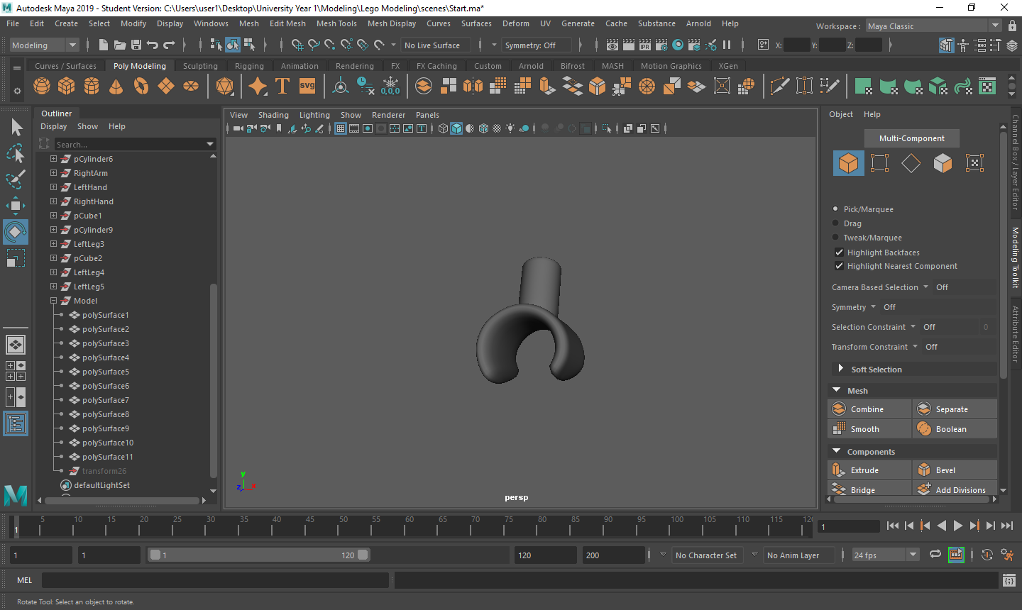
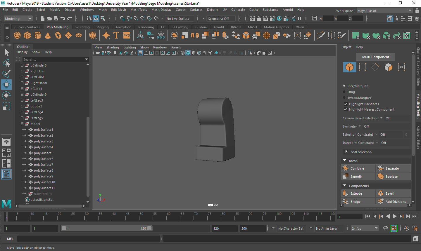
To finish off my model, I left the hardest part of the model to last. Firstly, I created a cylinder, and left the settings as default. I then rotated the z axis by 90 degrees to get the starting position I wanted. I then moved the cylinder up the waist, matching it with the center piece and scaling it out to match my reference images. I then deleted the faces of the cylinder from where one of the vertices was where I was going to extrude down, to the back of the leg. This is so I use the extrusion tool to create the rest of the leg I was missing. by selecting the edge loop where the faces were deleted I could achieve this, and I brought the extrusion down to where foot is supposed to come out. I then used the snap to vertex tool to make sure that the vertices I was bringing down were level so I make the rest of the extrusions. I make a second extrusion from where the foot is supposed to come out tot he bottom of the leg, then a final one for the foot. Filling the hole at the bottom of the foot I then had the basic shape I need to expand upon. To get the holes in the leg I needed, being a rectangle cut at the bottom and another through the leg so the model can stand, and two spherical cuts at the back of the leg so he can sit, I knew I had to use the boolean cut tool. I decided to do the rectangle cuts first. I created two rectangles and shaped them how the image had them, positioning them where I needed and made the cuts individually. I did this so I have a look around the shape and make sure that the object didn’t lose its edge flow. Once these cuts were completed and the shape was how I wanted it to be, I went onto the final cuts, where I used a cylinder with an axis of 8 to get the results I wanted. I created this object that I was using for the cut very long so I could see exactly where the cut was going, then duplicated the object so that I could get the two cuts I wanted. Using the same method as previous, I did these cuts separately so I could check around the object for anything that needed to be fixed. Most of the issues that came these 4 cuts were vertices. I noticed that there were a lot near each other that could be merged or some that when cut, would leave some edges that would disturb the edge flow. Fixing these issues wasn’t too difficult, as it was only a matter of moving the vertices so that they could be merged with other vertices that were in the position I need them to be. Once all issues were fixed, I finally added the beveling manually using the edge loop tool, duplicated the object and flipped it so that I had both legs to finish the model.

When we got handed the assignment, the groups all had to choose which real world games we were going to transform into LEGO. The only restriction being that they cannot already be a LEGO game, (e.g. Batman). With this in mind, I decided that I was going to make the Blizzard game, Overwatch, into LEGO as I am an avid fan of their content. I then went into Padlet to create a mind map of as many components I could possibly think of that I could recreate. After a couple hours of writing all of my theories down I then went onto creating a project in the project management software, JIRA. I will be using this to create tasks and sprints to keep myself in-line with the many hours that I have to put in to accomplish this assignment, and also to give me a clear direction on how I am going accomplish such goal. I will be stringing multiple tasks that have some relevancy to each other into sprints that show what work I have done, and also what work needs to be once a sprint has finished.
With all of these starting factors now in place, it is time to decide on what elements of this project I want to start first. The most logical starting point is to build a lot of the components, like bricks and models, so I can then animate and texture them later. Knowing this, I went into the software I will be using to create such components, Maya, and created a work space ready for me to start.
